In this tutorial, I have briefly explained how to use Raspberry Pi to build a smart automatic light control system using the BH1750 sensor.
Introduction
In today’s fast-moving world, lights have become an important and highly used appliance in building our environment. We use it for lighting our houses, growing indoor plants, street lights, etc. When it comes to street lights, lights play a major role in promoting safety and security to people during the night hours, which helps in the reduction of crimes and accidents. However, due to busy lifestyles and daily routine activities, manual switching operations of street lights are not done at the proper time. Because of this, lights are turned on even when there is an ample amount of sunlight. This leads to a huge wastage of electricity.
This tutorial demonstrate solutions to the above mentioned problem by building a smart automatic light control system using Raspberry Pi and BH1750 light intensity sensor. The built system will automatically switches the light ON and OFF based on the sunlight present in the environment using the BH1750 light intensity sensor.
Hardware Requirements
Raspberry Pi
Raspberry Pi is a tiny programmable device that comprises of GPIO (General Purpose Input Output) pins, Ethernet port, SD card slot, processor, USB port, RAM, HDMI, power source connector, and various other interfaces for connecting external devices. It is a very affordable computing device that runs on Linux Operating System. The GPIO digital pins acts as a physical interface between Raspberry Pi and external electronic components.
BH1750
BH1750 is a digital light intensity sensor that uses the I2C interface to obtain ambient light data from the surroundings. The sensor module comes with a built-in 16-bit AD converter to directly output a digital signal. The output produced by this sensor is the light intensity in terms of LUX, the SI unit for illuminance. It can accurately measure the light intensity up to 65535lx.Click BH1750 sensor datasheet for more details.
LED
A light-emitting diode (LED) is a semiconductor light source that uses a p-n junction diode to emit light when an electric current is introduced. In an LED, the positive pin (the long leg) is called the anode, and the negative pin (the flat edge) is called the cathode. The LED should be connected to the circuit in the right direction. That is, the anode of the LED should be at a higher potential than the cathode as the current in the LED flows from the anode (+) terminal to the cathode (-) terminal. In this tutorial, LED's are used as street lights, which switch ON automatically when the sunlight goes below the visible region of our eyes and turn off automatically when the day light is reached.
Breadboard and Jumper Wires
A breadboard is a rectangular plastic board with mounting holes which is used to build electronic circuitry without the need for soldering. It is commonly used to build prototypes and test electronic circuits before finalizing any circuit design. Electronic components like IC chips, resistors, switches, and sensors are connected to the breadboard via through-holes or jumper wires. The inside of the breadboard is made up of metal strips to hold wires or legs of any components.
Jumper wires are electrical wires insulated in a cable with a connector or pin at each end. It is used to establish connections between the Raspberry Pi and various different electrical components without soldering. Jumper wires are available in three forms: female-female, male-male, and male-female. The male wires have ends with solid pins that are meant to plug into the breadboard or other prototypes, and the female wires have ends with a hole in them to accept the male pin.
Circuit Connection
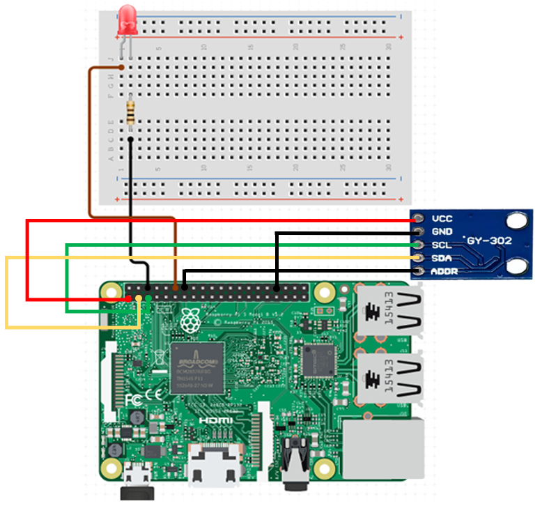
Do the following circuit connection with your Raspberry Pi turned off.1. Connect BH1750 sensor to the Raspberry Pi
- Vcc --> 3.3 V
- GND --> GND
- SDA --> GPIO 2 (SDA I2C)
- SCL --> GPIO 3 (SCL I2C)
- ADD (Address Select) --> GND
2. Connect LEDs to the Raspberry Pi
- Connect the anode (long leg) of the LED to Raspberry Pi's Pin 12 (GPIO18)
- Connect the cathode (flat edge) of the LED to one terminal of a 10KΩ (Brown Black Orange Gold) resistor.
- The other end of the resistor terminal is connected to the ground pin (GND) of Raspberry Pi.
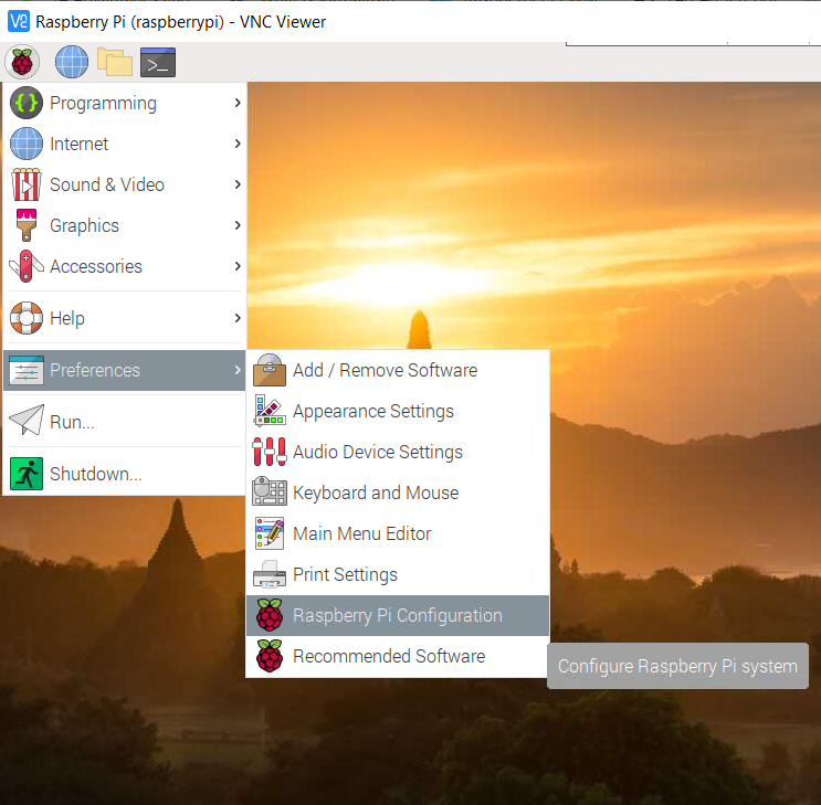
Configuring the Raspberry Pi
Enable I2C interface
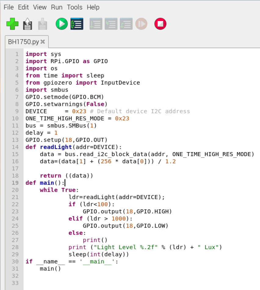
Python Code
Click the button below to download the python code. Change the "ldr" value (in Lux) in the above code as per your requirements.


0 Comments